Launch Controller
Nov 2025
A completely custom launch controller used for low and medium power rocketry launches. Designed and built from scratch, to be as reliable as possible at launch. I enclosed some simple electronics in a 3D printed body, with redundant launch controls and status LEDs. The foremost goal I had was safety, so I wanted to create a dependable launch system that was designed with safety features in mind, while also looking nice and being durable.
Project Requirements
-
Safe and reliable - no short-circuits, no need for field repairs, always launches when the correct steps are taken, correctly rated components
-
3-point system - a guarded power switch, arm button, and launch button
-
Status LEDs - 3 distinct colored and bright status LEDs: power, armed, and continuity
-
15-30' launch wires - to fulfill the NAR/CMASS's launch regulations, one must be at least 15-30' away (depending on motor being flown) before launching
-
Compact, portable, slightly weatherproof, and easy to use - convenient to bring to launches, able to survive in less ideal weather conditions (possibly covering the top face with a lid on a hinge), and usable with cold/gloved hands
Development
Electrical
I started work on this project with the electrical. This was my first time doing an electrical-centered project that wasn't for a flight computer, so I was a little out of my depth here. Fortunately, a friend of mine (one of the people who got me into rocketry in the first place) had made a similar controller of his own, and there are numerous articles and posts online of how to get started.
The circuit is based around two systems: a lower power control system, and a high power launch system. The thought was to separate the (relatively) low-amp-rated buttons from the igniter circuit. The control loop has power coming from the primary switch (which all power goes through, and it is rated for a high enough power), to the arm, and then the launch switch. It connects from there to an automotive relay (generally used for automotive purposes, but they were on Amazon and rated for 12V @ 30A). The power and arm LEDs just connect through this circuit. The igniter loop goes straight from the power switch to the relay, and then out to the actual igniter and back to ground, not going through any more buttons or switches than it has to. The third LED is for continuity: essentially a check to see if power can flow through the igniter, to make sure the igniter works and is ready for launch. The system does this through a amperage circuit going through the igniter, and back to power from the arm button (so the continuity check only happens when arm is hit, just in case). There is a higher ohm resistor on this circuit, to keep all the current at a minimum. I also had a 5A fuse directly on the power line, which should never trip during normal use (igniters at this level should pull 0.5-2A), although it should prevent serious damage during a short.
Prototyping
After the circuit diagram was made, I started work on the electrical prototyping, using a prototype board and some spare parts I had lying around, in place of the final switches and buttons I would use. This went mostly smoothly, although I had some issues with the continuity circuit and some resistors. After a few days of tinkering with wires and buttons, making edits to the diagram, and researching components, it was working fairly well!
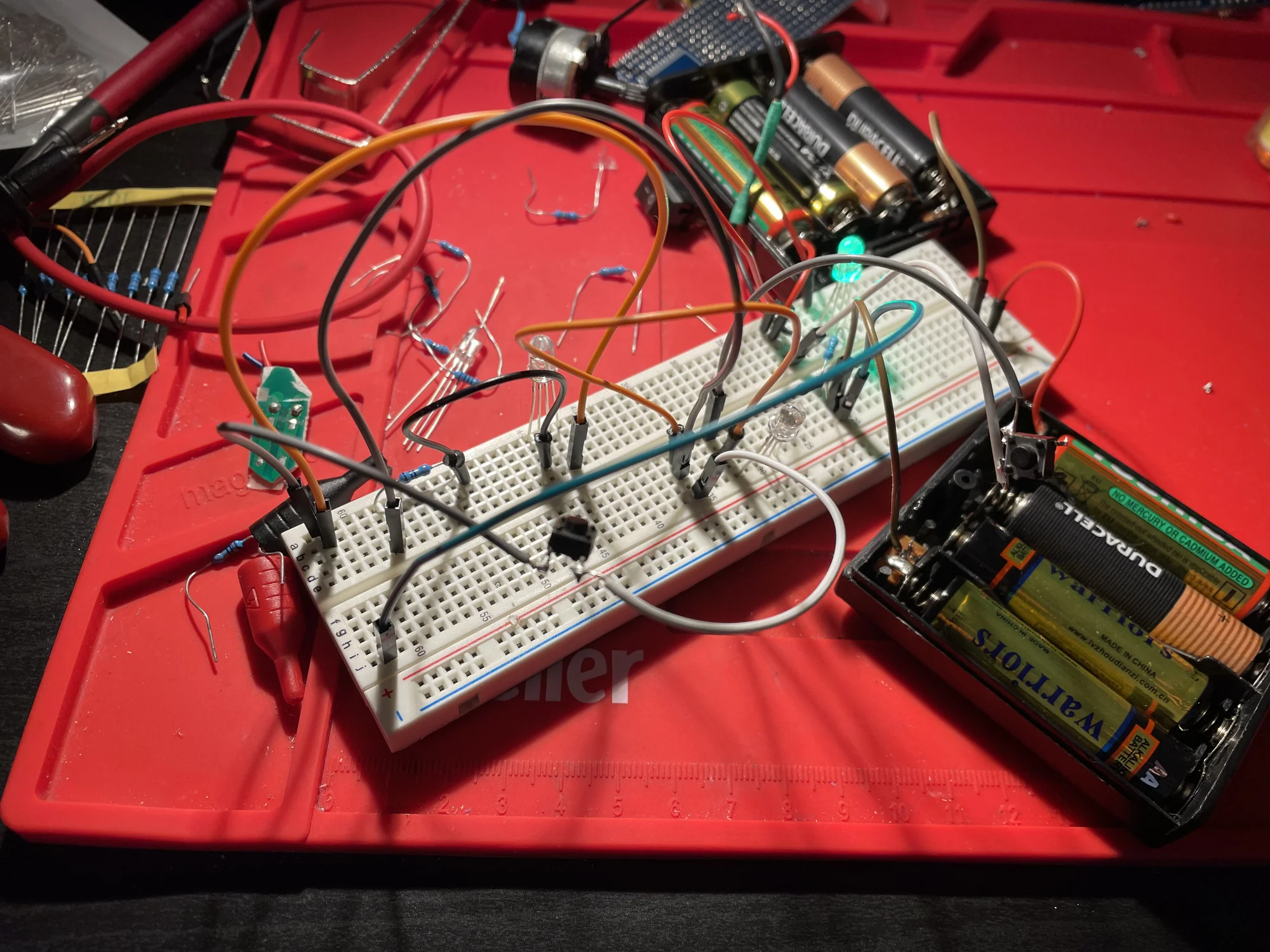
An early prototype of the circuitry
After this electrical prototyping, I moved to some 3D modeling. In Autodesk Fusion, I designed a 3D printed casing from scratch. My goal for the housing was for it to be easy to assemble/disassemble, with the batteries and electronics easily accessible (for when it inevitably breaks), but with it still looking nice and being a bit weather/water-proof. It had a 8 AA battery (which supplied the 12V) case built-in, based on the dimensions of two battery packs I had (which I also stole the electrical contacts from).
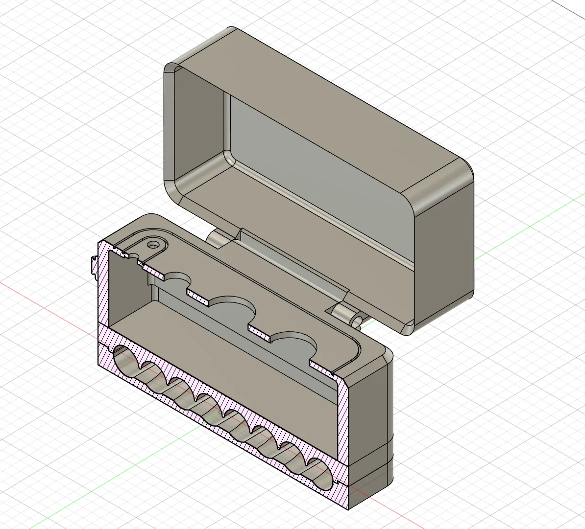
A cross-section view of the 3D design
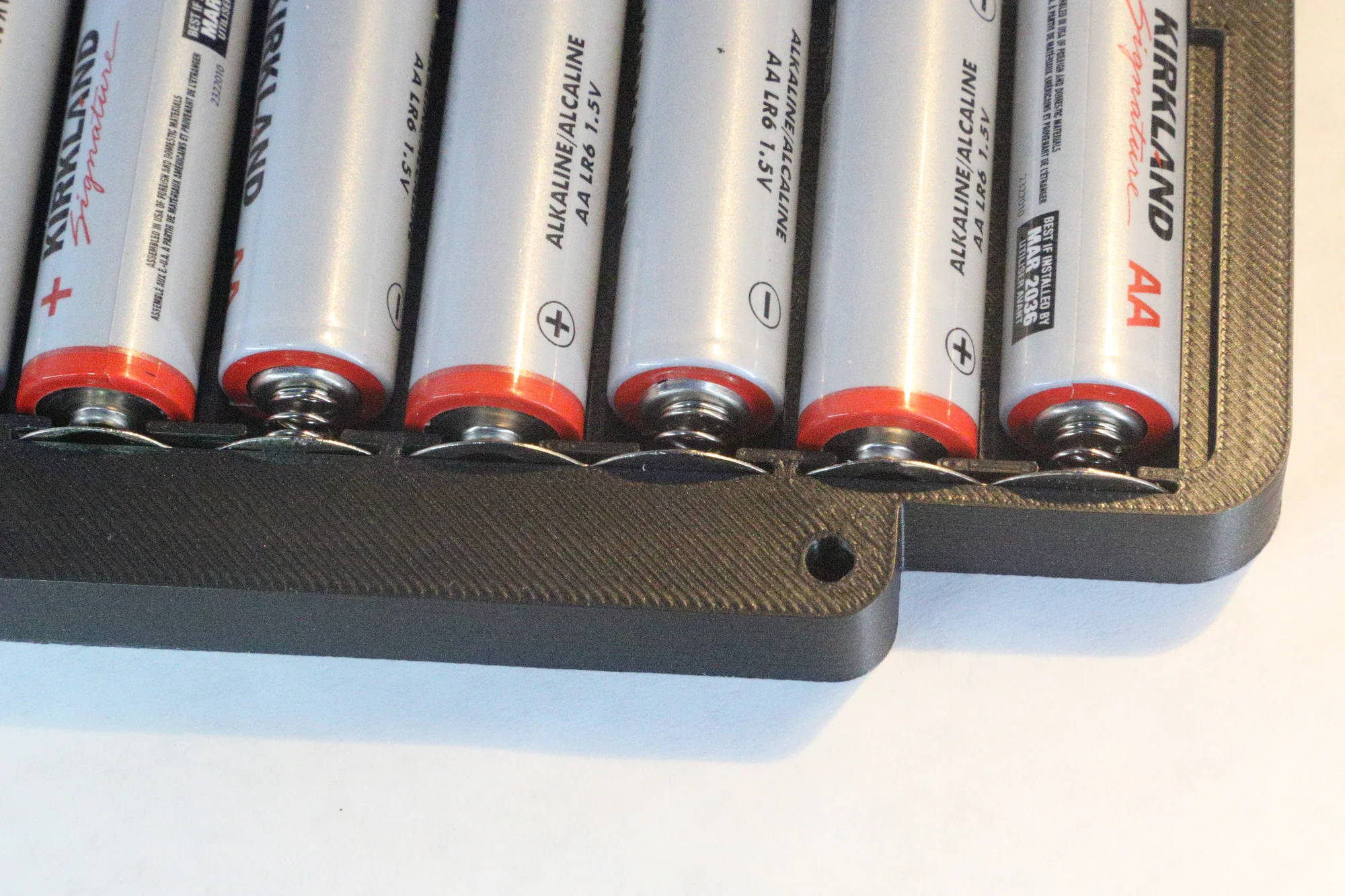
The 8x AA battery pack, and electrical contacts used
Final Build
At this point, the electrical components that I ordered had arrived, so I could start work on the final build. For the electrical side of things, I soldered a small circuit board for the control circuit and the LEDs, and connected it to 12V and ground. This was all wired with standard low current wires (I think 24 AWG). I used some basic RGB LEDs for the status lights, and just powered one pin so each would light up a different color (I could have done them as one LED because they were RGB, but I wanted it to be as clear as possible, so decided against it). For the igniter circuit, I used some lower gauge wire which could handle much higher current.
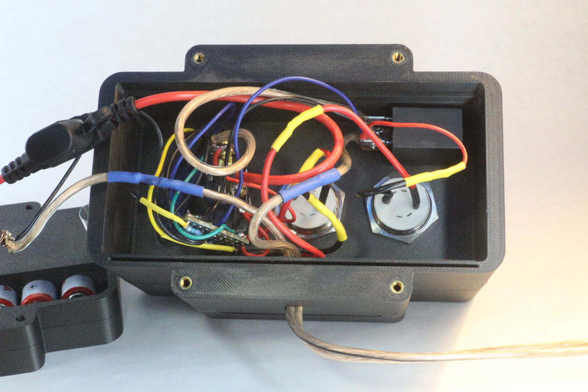
The electrical inside the final system
With the components here, I could measure them to get much more accurate fits, and I reprinted everything after a few iterations, in a nice-looking metallic PLA. I decided against painting this project, mainly because I just wanted it to be good enough to look at, and it didn't need a complex paint job (I also think hand sanding all of it would have been a pain). The final design I ended up with was made up of 3 layers. The first is a bottom battery case for the 8 AAs, the electrical contacts, and bolt holes. On top of this is a top part for the batteries to hold them snugly, and a gap for the power wires to go to the main compartment. This compartment makes up the majority of the build, and is a hollow section which houses the switch, buttons, LEDs, and most of the circuitry. The layers are connected with 4 M3 bolts and threaded inserts (small metal pieces with interior threads that can be heated and inserted into a plastic part with a soldering iron). I also added a lid, mainly in an effort to increase its durability and usability in all weather. There's a slight overlap on the edge of the lid, which creates a path for water to go straight down rather than onto the top of the control panel. The switch I am using is a guarded power switch, which works nicely for safety (and also looks cool). It automatically turns the switch off when the switch guard is closed, and closing the lid closes the switch guard (at past launches, I've noticed that sometimes we forgot to turn the power switch off after use, so I wanted it to be as easy and intuitive (and satisfying) as possible). As a last minute addition, I glued on some hooks and added a spring to the lid, to make it snap open and closed.
Finished Build and Usage
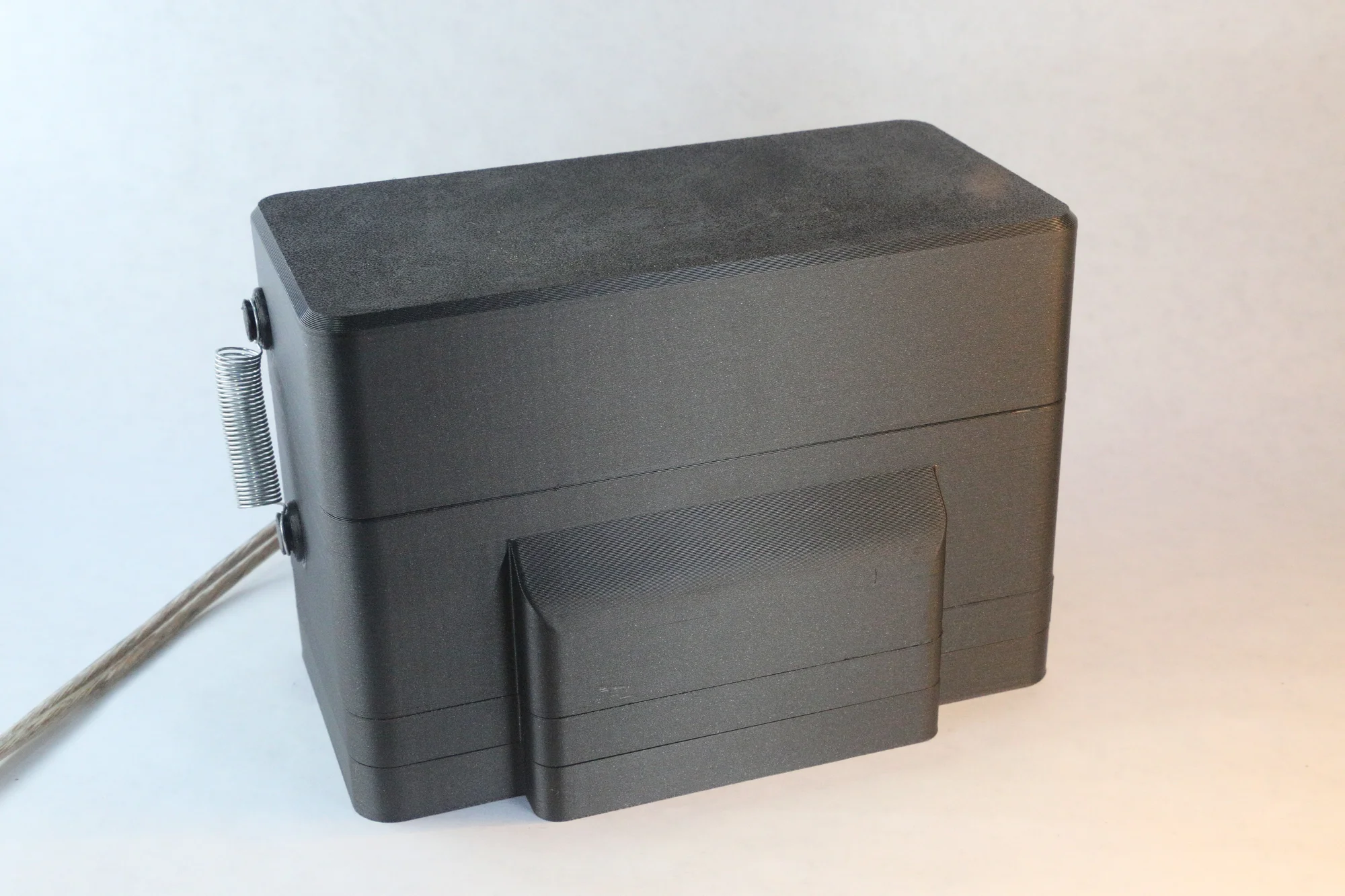
Final build - lid closed
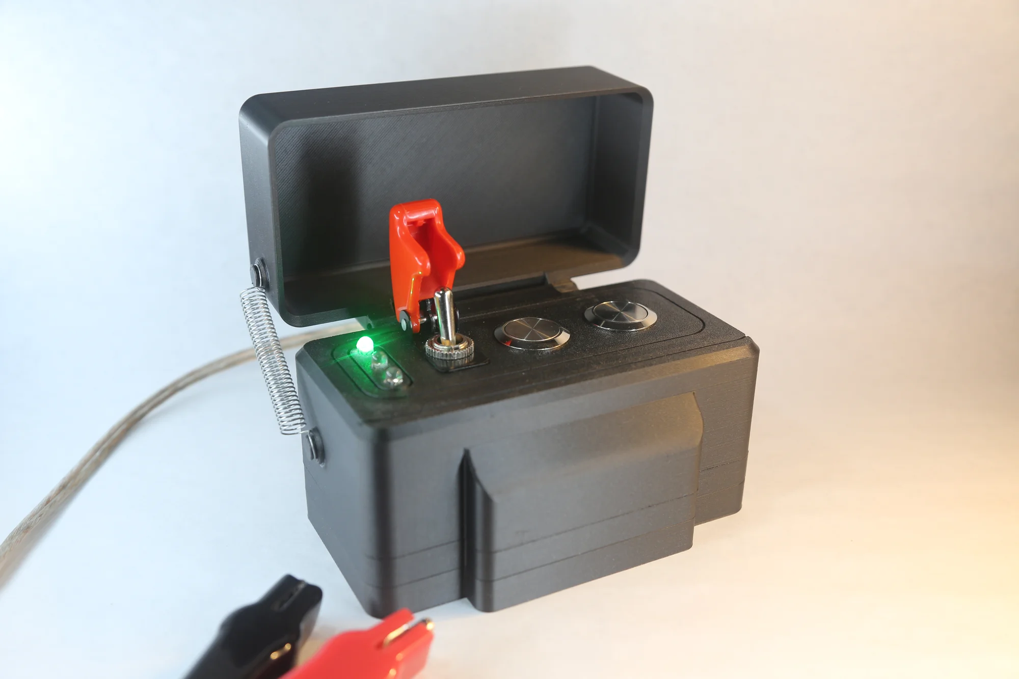
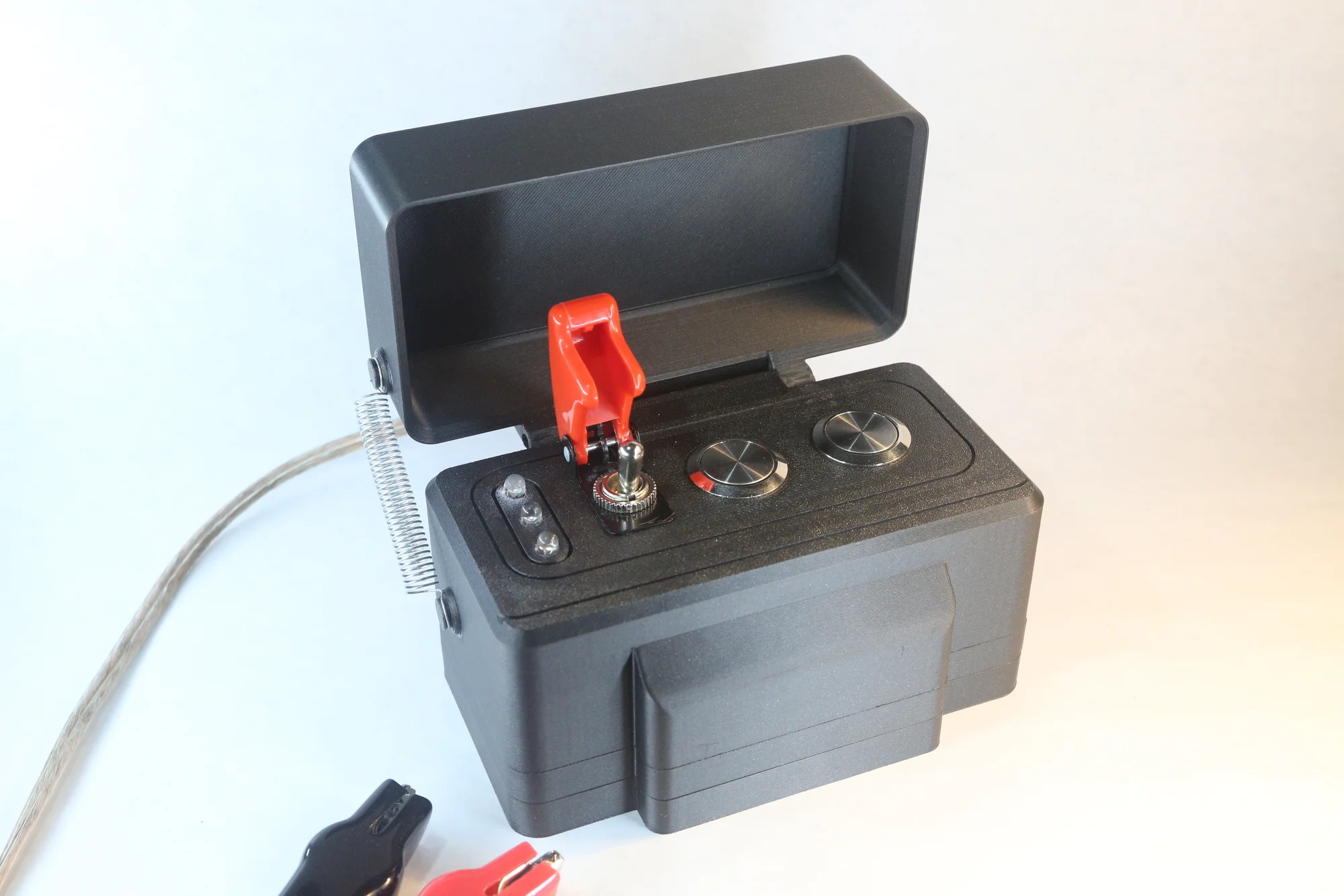
Final build - power switch on
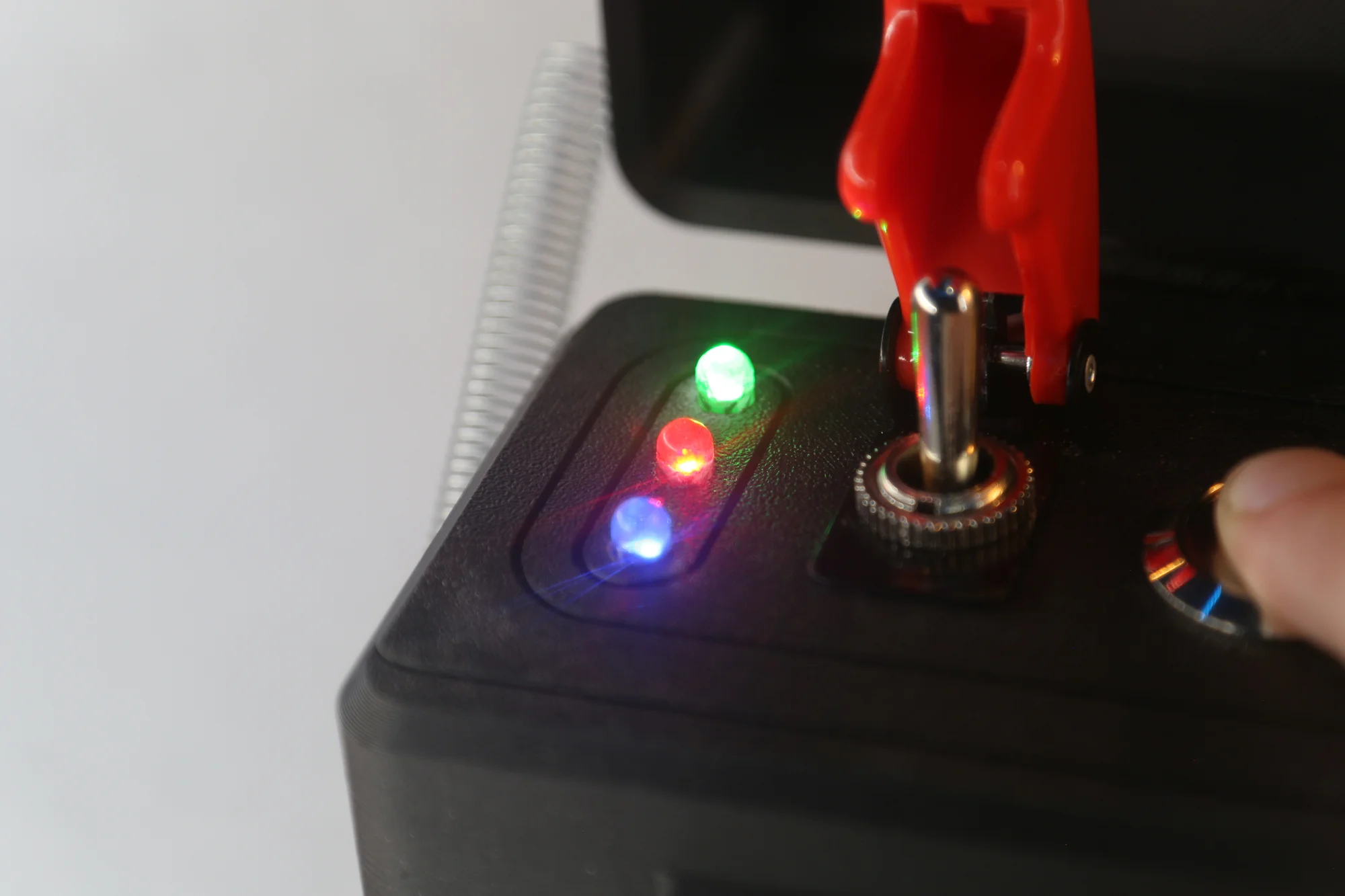
Final build - arm button clicked, with igniter continuity (the blue LED)
After doing a bench test on an igniter (which worked first try!), I felt ready to take it to an actual launch. I took it to a rocketry club launch in November, 2025, where it was the launch controller we used for motors from A to some Fs. It worked fine for all of them, with the continuity light fully functional (which was the main worry I had). The lid was especially nice, and it felt pretty durable.
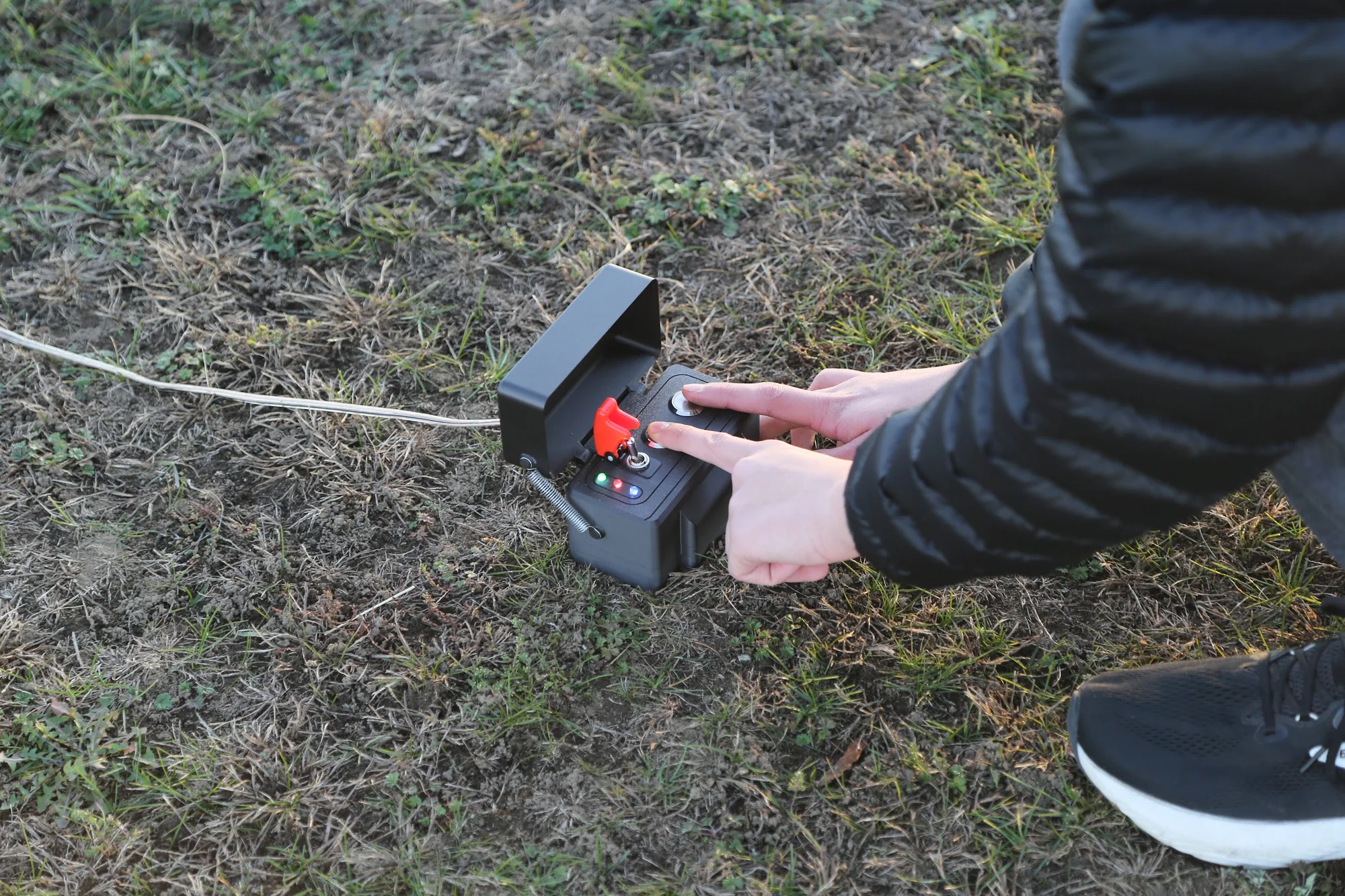
Launch controller being used at a launch
This was a project that I really enjoyed, and I'm looking to do more like it in the future! A lot of the electrical stuff was new for me, and it was really satisfying to make something that I'd actually use. I'm really satisfied with how the launch system turned out. I think it looks quite nice, and feels good to use. It is small and portable, and putting the batteries on the bottom makes it unlikely to tip over or move unintentionally. The LEDs are bright enough to use in sunlight, and the switches and buttons are good quality and feel sturdy.